Servo Motor Arduino
Oct 15, 2018 Introduction. I have used servo motors in several projects like the DIY Arduino & Bluetooth Robotic Arm, Web Controlled Servo using ESP8266, Arduino Joystick Interface to name a few. In fact, servo motors are one of the important components is projects where precise positioning is required.
Servo ArtThere is an optional feature that I haven't shown in the video, but it can be added to make the display interactive. It is purely optional, and the software will work fine without it.
For this option five ultrasonic distance sensors are mounted along the backside of the upper edge to the display. When you put your hand above the center sensor, the Uno goes into interactive mode, and all the servos attempt to follow your hand as you move it around above the distance sensors. When you remove your hand for a few seconds, the program returns to its display show. Again, you can add this option if you wish. If you don't, the software will work just fine without it. HardwareAs you can see, this project was built on a 24' by 48 ' piece of peg board.
The width was cut down to 32 inches. Servos are mounted 4 inches apart, and secured to the back of the peg board with hot glue. Popsicle sticks, cut down to 3 1/4 inches are mounted to the shafts of the servos, again using hot glue.The SG90 servo motors are the only costly item in this project.
You can get a set of 8 for $20 on Amazon. Even so, you need to invest $100 in servos. SG90s are suppose to all be 180º servos, but most don't quite make it. A few fall way short and should be discarded. If you buy 5 sets of 8, you should be able to find 36 goods ones that travel at least 160º.The servos need to be set to their minimum position (position at PWM 150), and the popsicle sticks mounted pointing horizontal and to the right in this minimum position, as viewed from the the front. I have provided a small program you can use to insure the servos are in this minimum position: SetServosToMinimum. Back Side of Servo ArtThe photo above shows the back side layout.
The three PWM controllers are mounted on the left side of the servos. The 30 watt 5 volt supply is on the far right. The Arduino is powered separately through a USB power adapter. I do it that way only so that I can unplug the USB cable and, through a USB extension cable, plug it into my computer for program changes. It looks a little weird, but I find it convenient.You can also see the optional ultrasound distance sensors mounted along the top of the display. Hot glue and extra popsicle sticks were employed to mount them.
The small prototyping board you see below the Uno is there simply to facilitate getting power and ground to all the ultrasound sensors. SoftwareI'm using Adafruit's PWM Servo Driver library to handle the 16 channel servo controllers, so you will need to get that from Adafruit and install in the Arduino libraries. My software can be used as is with or without the optional ultrasonic sensors.
It presents a variety of effects in a show that lasts a little over three minutes before repeating. If the optional sensors are installed, it will enter interactive mode whenever a hand is placed of the center sensor.There is a lot of stuff in the software. I will not attempt to explain the whole thing here, but I will give you a little info about how it works.
I have two tables. The curPos table stores the current position of each servo divided by three. The tarPos table stores the desired position of each servo divided by three. They are divided by 3 for two reasons. First, it allows them to be stored in a byte, and second, I am always moving the servos in increments of 3 steps.The Uno does not initially know the positions of each servo, so the setup routine sets all of the servos to a vertical position, and sets all curPos and tarPos variables to match that vertical position. We can then move the servos from there to other positions by changing the desired positions in tarPos.A subroutine called goToTargets is the primary way the servos are moved.
We control where the servos go by setting the targets at tarPos, Then we can control how fast they go there with the goToTargets routine. It has two ways to control the speed. It moves the servos toward their targets in 15 steps increments, where the reps input to the subroutine gives you multiples of 15 steps.
The other input is mydelay, which just adds a delay in milliseconds to each call of goToTargets.There is a lot of other stuff, but basically everything else is just various setups and implementations of the various effects presented.The optional interactive function is handled by subroutine called trackRoutine. It is called when the goToTarget routine sees an object (your hand) somewhere over the center ultrasonic sensor.
It attempts to make all the servos follow the motion of your hand as it moves over the sensors. When it hasn't sensed a hand for a few seconds it returns and the regular program resumes.
We have worked with basic DC motors a few times. We built a couple of and we also took an extensive look at the that is commonly used to regulate the speed and direction of a DC motor with a microcontroller or microcomputer.Another type of motor we’ve worked with is the stepper motor.
This type of motor has its shaft driven in discrete steps, allowing for very precise control. They are widely used in printer and robotics designs.There is another type of motor that we have used in many of our experiments but have not (yet) taken a detailed look at – the Servo Motor.A Servo Motor is a low-speed, high-torque motor that comes in a variety of sizes. Unlike the DC and Stepper motors the Servo Motor does not normally spin a full 360 degree rotation. Instead it is limited to a range of 180, 270 or 90 degrees.A control signal is sent to the servo to position the shaft at the desired angle.
This arrangement with a single signal makes it simple fo servos to be used in radio and remote controlled designs, as well as with microcontrollers.A servo is perfect if you need to position the rudder on a boat or the elevator on an aeroplane. They are really useful in robotic work to position cameras, sensors or robot appendages.Servos can also be used as analog gauges like speedometers and tachometers. Types of Servo MotorsA servo motor is essentially a motor that has an input for a control signal that is used to specify the position of the motor shaft.Servos are used in industry as well as in hobby applications.

Industrial servos are often AC motors with digital control inputs that cost hundreds or thousands of dollars.We will NOT be working with industrial servo motors today!Hobbyist servo motors are generally DC motors that can be controlled with either a digital or analog signal.Digital servos are used in applications that require quick responses like the elevator on an aeroplane or the rudder on a helicopter. We will NOT be working with these types of motors either, although the hookup and code used to drive them with an Arduino is identical to what we will use for our analog servos.We will be using plain ordinary analog servo motors, the most popular type for hobbyist use. They are inexpensive and easy to obtain. Mounting hardware is also very easy to find as these servos are of a standard set of sizes.It should be noted however that while we won’t be working with digital servo motors today they are really very much like their analog counterparts. They use the same PWM control signals as analog servo motors and can be controlled using the same circuitry and code. Analog Servo MotorsAnalog servo motors are inexpensive and available in a variety of sizes and ratings.
Perfect when you need a tiny high-torque motor that can be accurately positioned and that won’t break the bank.The “analog” part of the analog servo motor is the control signal. Analog servo motors respond to a Pulse Width Modulation or PWM signal to position their motor shaft.PWM is an ideal control medium. It can be generated by a simple timer circuit or with a microcontroller. It can be sent over a single wire or transmitted on a radio or light beam.The Arduino has a number of PWM capable output pins, making it ideal for controlling servo motors. How do Servos Work?A servo motor is a motor with a built-in “servomechanism”.The servomechanism uses a sensor to monitor the motor shaft position and a controller to control the motor. It is fed a signal that indicates the position that the shaft should be set to. It then moves the motor into the required position.In the analog servo motors we will be working with that control signal is a PWM signal whose pulse width determines the angle the motor shaft is to be positioned at.
The motor itself is a simple DC motor with a lot of gearing to slow down its speed and to increase its torque.In order to function properly the servo motor needs a sensor that can accurately measure its shaft position. On some industrial and high-end hobby servos this is done using an optical interrupter disc, but in most standard hobby servo motors the sensor is a potentiometer. This works well as these servos typically travel 180 to 270 degrees, well within the range of a potentiometer. However the accuracy of potentiometers, especially in low cost servo motors, can affect the overall accuracy of the servomechanism. Continuous Rotation Servo MotorsA standard analog servo motor is constricted in its rotation, usually to 180 or 270 degrees (180 is by far the most common).
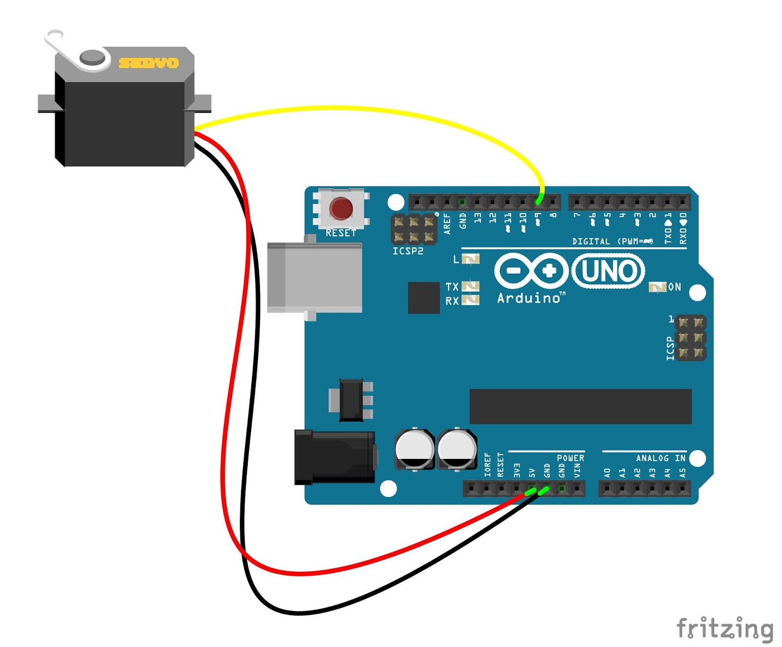
Its internal gearing provides a high torque power pack in a small and inexpensive package.That combination of small size and large torque also make servos attractive to use as replacements for standard DC motors in the design of small devices like tiny toys and robots. Sweep is a very basic sketch that just sweeps the servo shaft from one extreme to the other.The sketch makes use of the which is included with your Arduino IDE. As its name implies its is a library for controlling servo motors with PWM. We include the library and define an object called myservo to represent our servo motor. If you have multiple servo motors you can define an object for each of them.We then define a variable called “ pos ” that holds the position (angle) that we want the servo motor shaft to move to.In the setup we attach our servo object to the servo motor control line on pin 9 of the Arduino.Then the loop, which consists of two for loops. The first loop increments the value of the pos variable and uses it to control the servo motor using a myservo.write command, sending the shaft from 0 to 180 degrees.The second for loop is identical except it decrements the value from 180 to 0, sending the shaft back in the opposite direction.Load the sketch into the Arduino and observe the servo motor shaft, it should be travelling from one end to the other.You just made a servo move with an Arduino! The Knob SketchLet’s move on to the other demo sketch included with the Arduino IDE, the Knob sketch.
Before we do we’ll need to add a component to our circuit.As the wiring diagram shows you’ll need a potentiometer, any value from 10k up will work fine. Hook one end of the pot to ground, the other end to the Arduino +5 volts. The wiper is connected to analog input A0.The potentiometer will serve as a control to position the shaft of the servo motor, you can use it to dial any position on its 180 degree travel. Not only is it a good demonstration it also can be a useful function for setting the position of servo motors before mounting them into your project.If you substitute a continuous rotation servo in the circuit you can use the potentiometer to control both the speed and direction of the motor’s rotation.After you modify the experiment to include the potentiometer open the Arduino IDE and go back to the example sketches. This time select Sweep from the Servo menu.
The Sweep sketch is also very simple. Like the Knob sketch it uses the Arduino Servo Library which it includes and then creates a myservo object to represent the servo motor.We then define a couple of integers. The first one, potpin, represents the analog pin we used for the potentiometer wiper connection. The other one, val, is the value taken when reading that analog input.The setup is identical to the Knob sketch, we attach the servo object to pin 9.In the loop we start by reading the value from the analog pin, a value of 0 to 1023 which will be assigned to val. Next we use the Arduino Map Function to change val to represent the angle between 0 and 180 degrees.After that we use a write command to position the servo to the value of val, the angle selected by the potentiometer.After a brief delay to allow the servo motor to catch up we do it all over again.Load the sketch up to your Arduino and turn the potentiometer.
You should see the shaft of the servo motor move in time with the pot.Once again the sketch illustrates just how easy it is to control a servo with your Arduino. PCA9685 Servo Driver BoardControlling servo motors from an Arduino directly is pretty simple as we just saw. However it has its limitations:. You are limited by the number of PWM pins on your Arduino. If the servo is part of a design that requires other PWM devices that may be a problem.
The Arduino Servo Library can conflict with other Arduino libraries as they attempt to use the same timer. This can sometimes be solved by looking for alternative libraries. You need to control a LOT of servo motors, even an Arduino Mega has its limitations here.A better solution all around is to use a separate servo driver board. This will offload the task of sending PWM to the servos, freeing up your Arduino to do better things.The board we will be using is based around the PCA9685 chip. These boards are extremely popular and are manufactured by several companies.The PCA9685 board uses I2C to communicate with the Arduino.
This means only two connections for clock and data are made to the Arduino. As the boards I2C address can be configured using a series of solder pads you can use many of them on the same circuit.Each board can control up to 16 servo motors. And you can cascade up to 62 boards to control a whopping 992 servo motors!If you honestly need to control over 992 servo motors you could use an I2C shield to connect multiple I2C buses to your Arduino!The connections to the board are very simple.There are a set of identical connections on each side of the circuit board, this makes it easy to connect several modules up in a row.
They are as follows:. GND – The Ground connection.
OE – Output enable. You can use this pin to enable and disable all of the 16 outputs. Typically it is left unconnected which will result in all outputs being enabled. SCL – The Clock line for the I2C bus. SDA – The Data line for the I2C bus. VCC – The logic power supply, +5 Volts.
V+ – the power for the servo motors. There is also another connector on top of the board for this and that connector is preferable as it is reverse polarity protected while V+ is not. The V+ pins are really used to cascade multiple PCA9685 modules and power all the servos off of a single power supply.There is also a 2-pin screw connector at the top for the servo power supply.
As mentioned above it is reverse polarity protected.On the bottom of the board are 16 sets of 3-pin male connectors. Each one is used for a servo motor.On the top right of the board are six solder pads. These are used to setup the I2C address for the board. If you are using more than one board you’ll need to jumper one or more of these to change its internal I2C address to be unique.The base address for a PCA9685 module with none of the jumpers shorted is 0x40.If you short out the A0 solder pad the address becomes 0x41.Bridge A1 instead and it’s now an address of 0x42.
Bridge both A0 and A1 and the address will be 0x43. Multiple Servos – Controlling the MeArmIn order to demonstrate the use of the PCA9685 PWM module to control multiple servo motors I decided to bring out the MeArm which I built earlier. It has four servo motors.I connected everything up as follows:You’ll notice that I also added four potentiometers, as before these can be any value of 10k or above and will be used to regulate the operation of each of the four servo motors.The PCA9685 module hooks up to the SCL and SDA connections on the Arduino. If your Arduino does not have pins for these I2C connections then use analog pin A4 for SDA and pin A5 for SCL.Note that even if you do have separate SCL and SDA pins you won’t be able to use A4 and A5 as analog inputs when using I2C.The four potentiometers connect to ground on one side and 5 volts on the other. Their wipers connect to analog inputs A0 through A3.The Arduino power is also used to power the VCC power on the PCA9685 module. A seperate power supply for the four servos is connected to the screw connector on the module.I connected my servo motors to outputs 0, 4, 8 and 12. You can actually use any four connections, just note them so you can modify the code to match your selection.As this is the only PCA9685 module I’ve connected to the Arduino I didn’t short out any of the address solder pads.Now let’s look at the sketch I’m using to make this all work.
The sketch makes use of the Adafruit PWM Servo Driver Library which you will need to install to make this work. It can be installed from the Library Manager in your Arduino IDE. Open the Arduino IDE. Select Sketch from the menu at top. Select Include Library. A sub-menu will appear.
Select Manage Libraries from the sub-menu. The Library Manager will open. Search the Library Manager for “Adafruit PWM”. The Adafruit PWM Servo Library Driver should be the first result. Click the More Info link to reveal an Install button. Use this button to install the library into your IDE.
Close the library manager. The library is now installed and can be used in your IDE.We begin the sketch by including the Wire library. This is built into your Arduino IDE and is used to control I2C communications.Next we include the Adafruit PWM Servo Library that we just installed.We will now define a few constants.The first two constants define the minimum and maximum pulse width for the PWM signal we will be sending to our servos. A you recall this pulse width will determine the position of the servo shaft.The third constant we define is the PWM frequency, which for analog servo motors is 50 Hz. If you are using digital servo motors you may want to increase this as they can often use frequencies as high as 200 Hz.Next we create an object called pwm using the Adafruit PWM Library. If you used an address other than the default 0x40 you would need to define it here.Now we define some variables.
The first one is the potentiometer input pins, A0 through A3. After that are the motor outputs on the PCA9685 board, I used 0, 4, 8 and 12 when I hooked up my motors. Change these values if you used different connectors for your motors.Now onto the Setup.
We initialize the pwm object we created earlier and then set the frequency of the PWM oscillator to the frequency we defined, which in our case is 50 Hz.Now we create a function that will drive the motors in response to the potentiometer positions. We can then just call this function for each motor.Our function is called moveMotor. It has two inputs, controlIn which represents the potentiometer input and motorOut which represents the motor connection on the PCA9685.The function reads the potentiometer value and converts it to a pulse width.
This pulse width is then used with the setPWM method of the Adafruit PWM Servo Library to send the pulse to the motor specified by the motorOut variable.In the loop we just call the moveMotor function four times, once for each potentiometer-servo motor combination.The result is that the four servo motors in the MeArm will respond to the potentiometers. In the demo I used slide potentiometers which made it a lot easier to precisely position the MeArm (I use the term “precisely” with a lot of poetic license!). ConclusionServo motors are versatile little devices that have a myriad of uses in hobbyist projects and knowing how to control them is an essential Arduino coding and wiring skill.Hopefully this article and its associated video have helped shed some light on using servo motors, either connected directly to an Arduino or via I2C using a PCA9685 PWM controller.So grab yourself a bunch of servo motors and start making things move today!.If you have a question.Comments about this article are encouraged and appreciated.
However, due to the large volume of comments that I receive, it may not be possible for me to answer you directly here on the website.You are much more likely to get answers to technical questions by making a post on the.Your post will be seen not only by myself, but by a large group of tech enthusiasts who can quickly answer your question. You may also add code samples, images and videos to your forum posts.Having said that, please feel free to leave constructive comments here.
Your input is always welcome. Please note that all comments may be held for moderation. Concerning this particular board and researching the data sheets, I can NOT find a definitive answer to this question; Is it possible to control different types of servos that require a different PWM on this board OR are multiple boards needed?? IF possible, how would one go about “addressing and configuring” said motors?? I’m building a Bot consisting of a 6DOF Arm mounted on a tracked chassis. The Chassis will have 2 brushless motors with board to power. The 6DOF has 4 “Standard” size servos and 2 “Mini” for wrist rotate and Grip.
The servos require different PWM. A good Read more ».